Lompat ke konten Lompat ke sidebar Lompat ke footer

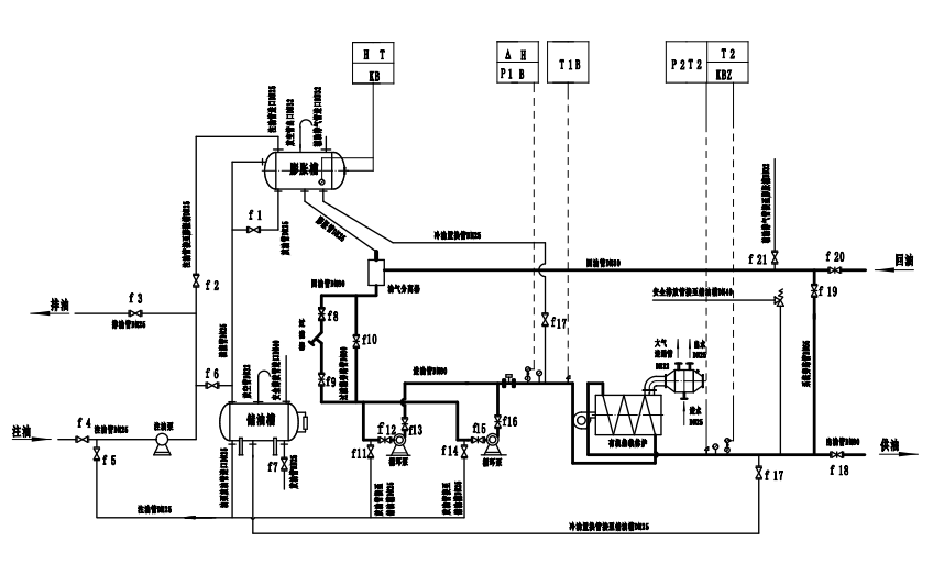
Hot Oil System Process Flow Diagram

Closed Loop Process Flow Diagram Of Hot Oil System As Per Shell Dep Download Scientific Diagram

Closed Loop Process Flow Diagram Of Hot Oil System As Per Shell Dep Download Scientific Diagram

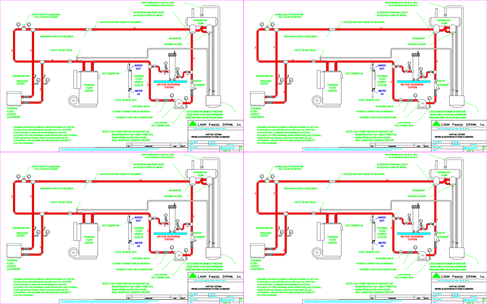
Hot oil system process flow diagram. Pre-drawn process heating symbols represent batch oven calendar circulation heater compensator condenser evaporator expansion loop heat exchanger etc. Axens H-Oil Process - Flexibility. An expansion tank vented to atmosphere and elevated above the system maintains a constant positive suction head on the pump.

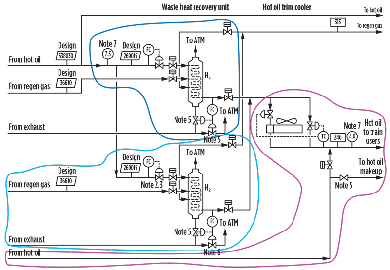
Teheran - November 2017. Fig2 describes similar process flow diagram of hot oil system commonly employed in oil and gas plants. Solar Heating - Direct Pumped System.

This is what is colloquially known as the first smoke pass. The catalyst is continuously regenerated. Widely used in process industries especially in oil and gas plants as a heating medium hot oil is.

A10 Diesel Hydrodesulfurisation Unit DHDS The purpose of this unit is to hydrotreat a blend of gas oil diesel oil and kerosene or LCO in order to produce a low sulphur content gas oil. Não possui uma conta. Oil and Gas Processing Oil Section The typical process flow diagram PFD of oil and gas processing for most of fixed or floating offshore production.

H-Oil Overall Block Flow Diagram Outstanding catalytic system H-Oil ACS. It must be designed in accordance with the appropriate codes. The level of detail can be decided by the team.

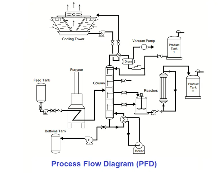
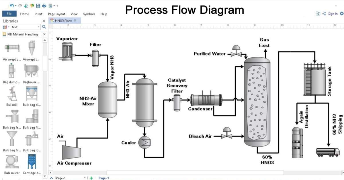
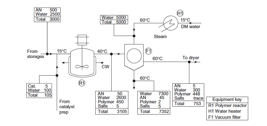
A PFD helps with the brainstorming and communication of the process design. Process Flow Diagrams PFDs are a graphical way of describing a process its constituent tasks and their sequence. PID Process Heating Symbols and Their Usage.

The Complete Process diagram is given in Fig. Heat should be applied in 20F 11C to 25F 14C increments until the heat transfer fluid gets to a viscosity of 10 cP centipoise or less.

A General Process Flow Diagram Of Hot Oil System Commonly Employed In Download Scientific Diagram

A General Process Flow Diagram Of Hot Oil System Commonly Employed In Download Scientific Diagram

10 Tips Hot Oil Systems 2004 09 01 Process Heating

10 Tips Hot Oil Systems 2004 09 01 Process Heating

Pdf A Techincal Report On Design Of Hot Oil System

Pdf A Techincal Report On Design Of Hot Oil System

Mokon Hot Oil Htf 500 Circulating Process Control Systems

Mokon Hot Oil Htf 500 Circulating Process Control Systems

Operating A Hot Oil Heat Transfer Fluid System

Operating A Hot Oil Heat Transfer Fluid System

A General Process Flow Diagram Of Hot Oil System Commonly Employed In Download Scientific Diagram

A General Process Flow Diagram Of Hot Oil System Commonly Employed In Download Scientific Diagram

Hot Oil System Chemical Engineering Portal

Hot Oil System Chemical Engineering Portal

10 Tips Hot Oil Systems 2004 09 01 Process Heating

10 Tips Hot Oil Systems 2004 09 01 Process Heating

2

2

P Id In Thermal Oil Circuits Pirobloc

P Id In Thermal Oil Circuits Pirobloc

Crude Oil Distillation Unit Pfd Process Flow Diagram Symbols Process Flow Diagram Draw And Label The Diagram Of Crude Oil

Crude Oil Distillation Unit Pfd Process Flow Diagram Symbols Process Flow Diagram Draw And Label The Diagram Of Crude Oil

Hot Oil Heating Process

Hot Oil Heating Process

Hot Oil Heaters And Thermal Fluids The Complete Guide Pirobloc

Hot Oil Heaters And Thermal Fluids The Complete Guide Pirobloc

Thermal Oil Heater Working Principle Youtube

Thermal Oil Heater Working Principle Youtube

2

2

Hot Oil Heaters And Thermal Fluids The Complete Guide Pirobloc

Hot Oil Heaters And Thermal Fluids The Complete Guide Pirobloc

Base Case Process Flow Diagram The Temperature Of The Streams Is In Download Scientific Diagram

Base Case Process Flow Diagram The Temperature Of The Streams Is In Download Scientific Diagram

Brochures On Hot Oil Filtration Vector Vector With Bypass And Stand Alone Sentinel Portable Systems

Brochures On Hot Oil Filtration Vector Vector With Bypass And Stand Alone Sentinel Portable Systems

Typical Process Flow Diagrams Pfds Enggcyclopedia

Typical Process Flow Diagrams Pfds Enggcyclopedia

2

2

What Is A Process Flow Diagram Pfd

What Is A Process Flow Diagram Pfd

Piping And Instrument Diagrams P Ids Part 1 Origin And Evolution

Piping And Instrument Diagrams P Ids Part 1 Origin And Evolution

Process Flow Diagram A Process Configuration With Heat Supplied By Download Scientific Diagram

Process Flow Diagram A Process Configuration With Heat Supplied By Download Scientific Diagram

1

1

Thermal Expansion Tank Design And Operation 2014 06 02 Process Heating

Thermal Expansion Tank Design And Operation 2014 06 02 Process Heating

Hot Oil Heaters And Thermal Fluids The Complete Guide Pirobloc

Hot Oil Heaters And Thermal Fluids The Complete Guide Pirobloc

Htf Hf 2 Heat Transfer Oil System Mokon Temperature Control Units

Htf Hf 2 Heat Transfer Oil System Mokon Temperature Control Units

Difference Between Pfd And P Id With Example Inst Tools

Difference Between Pfd And P Id With Example Inst Tools

Thermal Oil Heater Thermal Oil Boiler Hot Oil Heater

Thermal Oil Heater Thermal Oil Boiler Hot Oil Heater

Lube Oil System An Overview Sciencedirect Topics

Lube Oil System An Overview Sciencedirect Topics

10 Tips Hot Oil Systems 2004 09 01 Process Heating

10 Tips Hot Oil Systems 2004 09 01 Process Heating

Heat Transfer Enhancement Using Co2 In A Natural Circulation Loop Scientific Reports

Heat Transfer Enhancement Using Co2 In A Natural Circulation Loop Scientific Reports

Simplified Flow Chart Of The Residual Oil Recovery System Process Download Scientific Diagram

Simplified Flow Chart Of The Residual Oil Recovery System Process Download Scientific Diagram

P Id In Thermal Oil Circuits Pirobloc

P Id In Thermal Oil Circuits Pirobloc

Process Flow Diagram An Overview Sciencedirect Topics

Process Flow Diagram An Overview Sciencedirect Topics

Oil Gas Fired Thermic Fluid Heater Thermic Fluid Heaters Thermopack Products Energy Process Equipments

Oil Gas Fired Thermic Fluid Heater Thermic Fluid Heaters Thermopack Products Energy Process Equipments

2

2

Process Flow Diagram Pfd Chemical Engineering World

Process Flow Diagram Pfd Chemical Engineering World

P Id In Thermal Oil Circuits Pirobloc

P Id In Thermal Oil Circuits Pirobloc

Marine Boiler Combustion Process Arrangement Supply Of Fuel Oil

Marine Boiler Combustion Process Arrangement Supply Of Fuel Oil

What Is A Process Flow Diagram Pfd

What Is A Process Flow Diagram Pfd

Process Flow Diagram Processdesign

Process Flow Diagram Processdesign

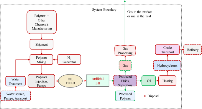
Chemical Enhanced Oil Recovery And The Dilemma Of More And Cleaner Energy Scientific Reports

Chemical Enhanced Oil Recovery And The Dilemma Of More And Cleaner Energy Scientific Reports

Process Flow Diagram Feedstock Recycling Benefits Of Recycling

Process Flow Diagram Feedstock Recycling Benefits Of Recycling

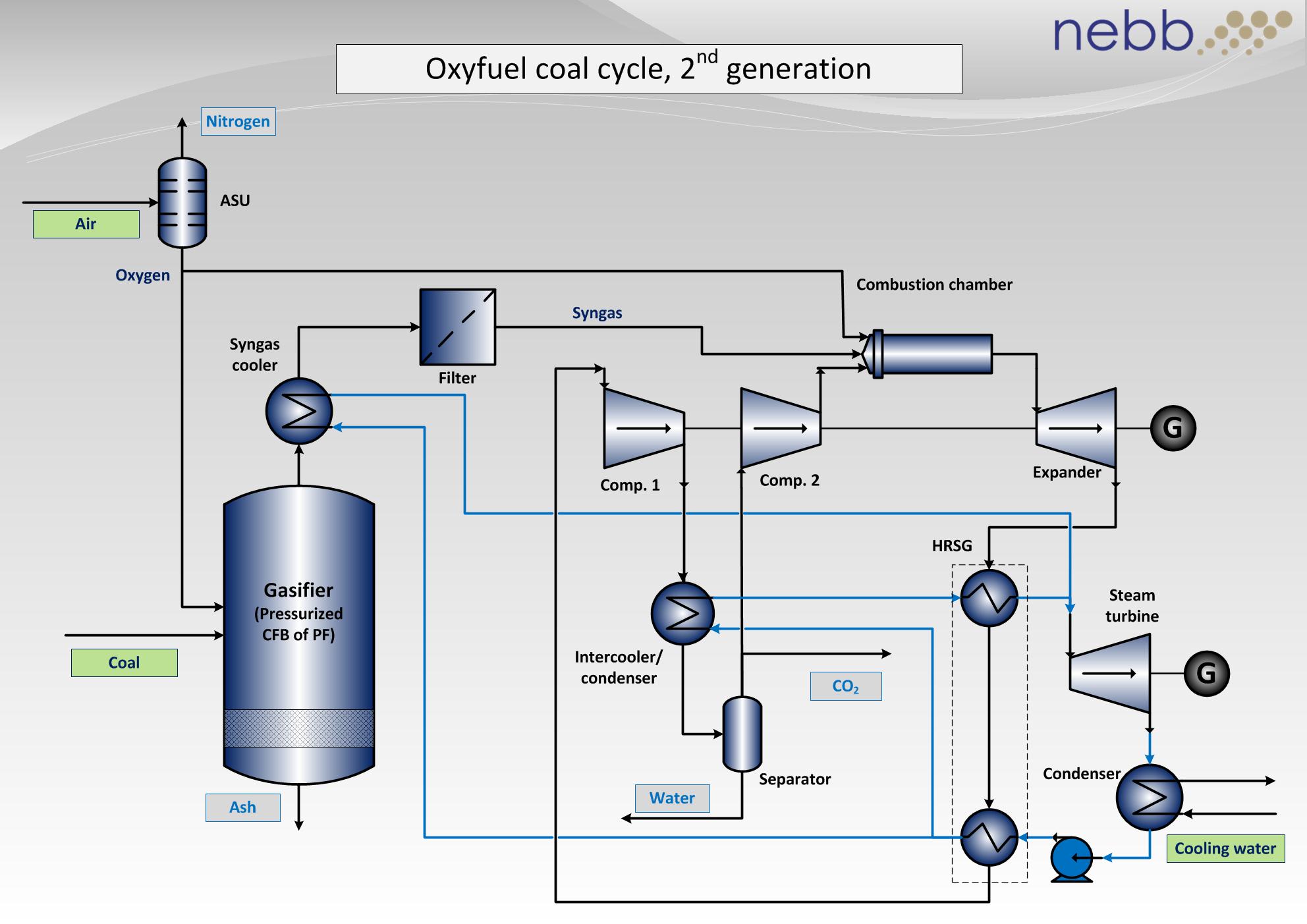
Oxyfuel Coal

Oxyfuel Coal

Scielo Brasil Modeling Of Multiphase Flow In An Air Cooling System Using The Cfd Fsca Approach Modeling Of Multiphase Flow In An Air Cooling System Using The Cfd Fsca Approach

Scielo Brasil Modeling Of Multiphase Flow In An Air Cooling System Using The Cfd Fsca Approach Modeling Of Multiphase Flow In An Air Cooling System Using The Cfd Fsca Approach

What Is A Process Flow Diagram Pfd

What Is A Process Flow Diagram Pfd

10 Tips Hot Oil Systems 2004 09 01 Process Heating

10 Tips Hot Oil Systems 2004 09 01 Process Heating

1

1

A PFD helps with the brainstorming and communication of the process design.

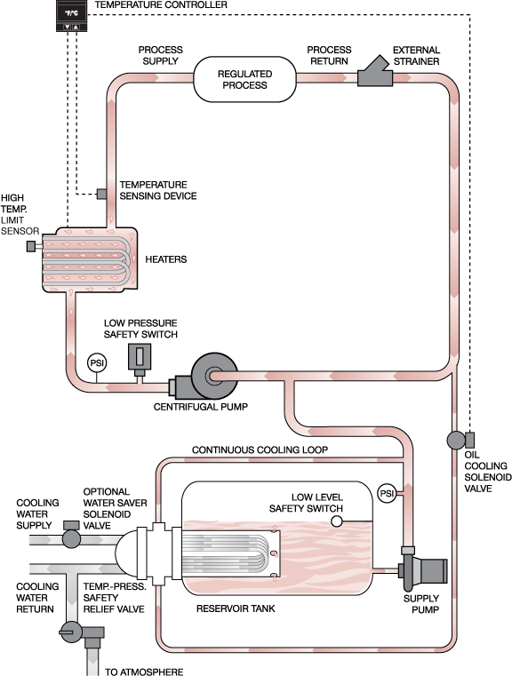
76 Process Steam Generation by the Package Boiler Process-Base Case Process Flow Diagram D-3 77 Cogeneration of Steam and Electricity by the Combined Cycle Process Process Flow Diagram D-5 81 Pressure Swing Adsorption PSA Process for Nitrogen Separation 8-3 82 Membrane Process Flow Diagram for Nitrogen Sep aration 8-5. Ad Use Lucidchart to visualize ideas make charts diagrams more. Heat should be applied in 20F 11C to 25F 14C increments until the heat transfer fluid gets to a viscosity of 10 cP centipoise or less. A PFD helps with the brainstorming and communication of the process design. Flow Diagram The heat transfer fluid is circulated through the electric heaters and the process in a closed loop. Vector symbols help develop accurate and presentation-quality diagrams and documentations. Find out why pros choose Lucidcharts to make process diagrams. It must be designed in accordance with the appropriate codes. Create Process Flow Diagram examples like this template called Solar Heating - Direct Pumped System that you can easily edit.


First you start your system pump to get the fluid flowing through the system. Axens H-Oil Process - Flexibility. Widely used in process industries especially in oil and gas plants as a heating medium hot oil is. The transfer of process heat as a liquid offers these System 1 is the basic system configuration with a single benefits to the installation. Teheran - November 2017. Heat should be applied in 20F 11C to 25F 14C increments until the heat transfer fluid gets to a viscosity of 10 cP centipoise or less. Vegetable oil refinery plant hot soybean oil refining process palm oil processing hine flow chart of palm kernel oil refining small scale edible oil refinery line.

Posting Komentar untuk "Hot Oil System Process Flow Diagram"